This week we went over buttons/switches, LED’s, and resistors. We also plugged in a 7805 5VDC voltage regulator.
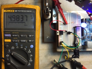
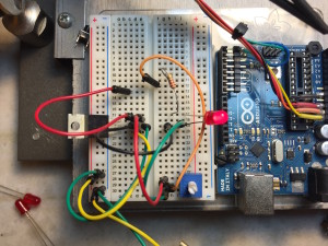
Starting with the 7805:
Looks like its doing its job! The meter is measuring voltage across the blue LED and the 220Ohm 1/8 watt resistor.
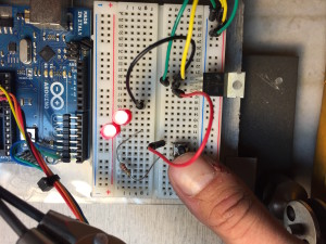
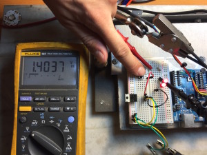
Up next we have two red LED’s in series with a 220Ohm resistor:
The 220Ohm resistor is drawing 1.4VDC.
Next up we have three red LED’s in parallel. I have lifted the left LED’s anode and put my amp meter in parallel. These sissy LED’s are only drawing 1.4mA.
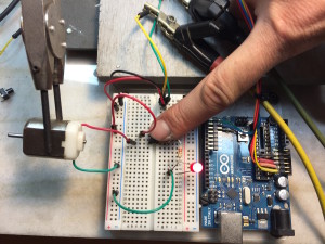
Here we have an LED and a little motor in parallel:
And finally a voltage divider made with a 10Kohm potentiometer:
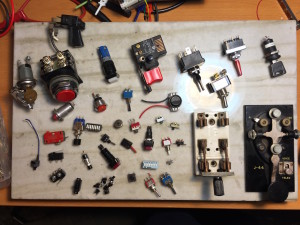
And now some switches! Not sure which one to use 🙂
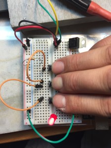
Here are three normally-open push buttons in parallel:
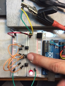
And here they are in series:
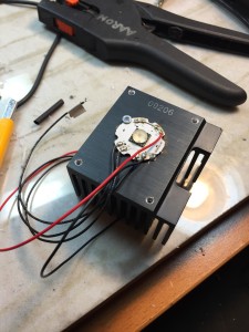
For my switch project I decided to have some fun with a 40watt RGBW LED. I stated by mounting it to an old pentium III heatsink, with some thermal compound in between:
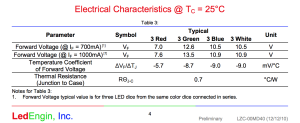
Next I went to the data sheet. I’ve had this thing for four years . . . luckily mouser saves your purchase orders 🙂
I found the forward voltage ratings and decided to run this thing at 12VDC. The Green diodes forward voltage starts at 12.8V, but Im sure it’ll look fine at 12V. These are some big numbers to be seen for an LED. This LED certainly must be a package containing several dies per color. . .
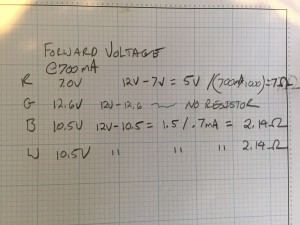
Even my awful math skills can figure this out 🙂
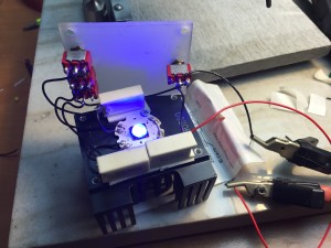
Next we add some switches:
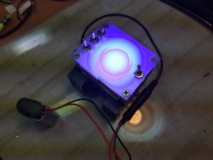
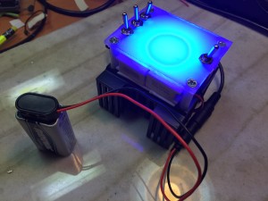
Here is the final product!
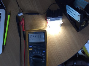
Looks like we are drawing a happy healthy 520mA with a 12VDC input. For the white, the closest high power resistor I had was 3.9ohms instead of the 2.14ohms I calculated.
This guy is painfully bright at 12VDC, so I think for class I will stick with a 9V battery.
